1.3. Scene Editor
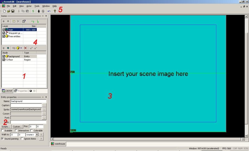
As both scenes in the demo have too many things going on, we’ll start with something simpler. In the Project Manager right click the folder scenes and choose Add scene. From the left side choose a template “Empty Scene 800x600” and name the scene warehouse. Then locate the folder warehouse in your sandbox→scenes folder and copy the contents of Chapter 1 resources inside. Double click on the warehouse.scene in the Project Manager to open a Scene Editor.
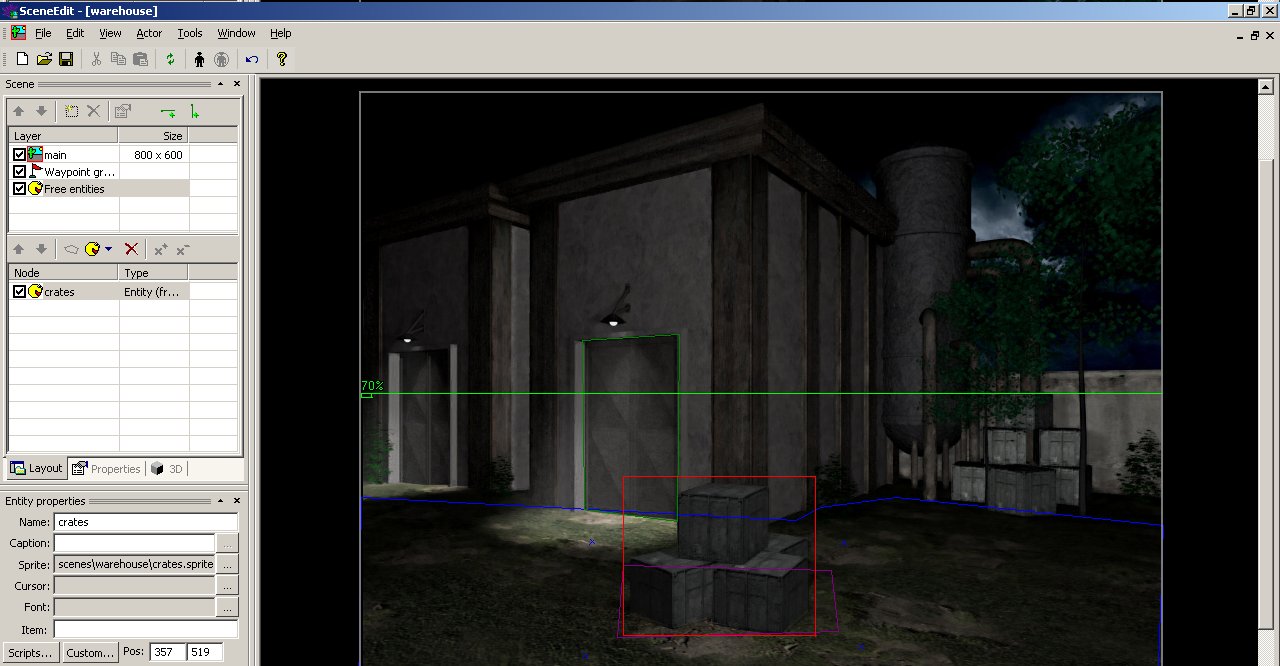
You can see in the section 4 that your scene can consist of many layers, but we’ve selected the main layer for now and we’ll get to the purpose of multiple layers later. Also you see there Waypoint groups and Free entities. Let’s demonstrate how to use them after we get used to the logic of our Scene editing.
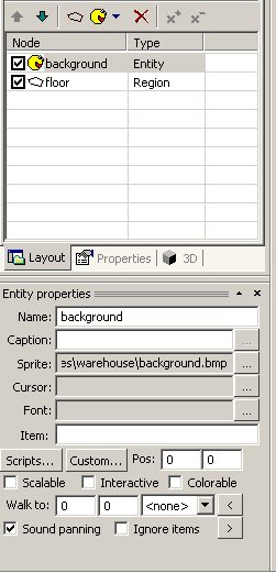
For now we’ll focus on sections one and two:
Tip: You can see that next to each scene element in the Scene Editor is a little checkbox. You can uncheck it to make the Node invisible and disabled at the same time. Shortcut for that is a keyboard
key “space”. This sets the internal attribute of the Node called Active to either true or false. More on that comes later.
Before we try to experiment with the scene, let’s clarify a couple of terms again. In WME each element of the scene is called Node. It’s important later because you can from your script reference every scene node. Now let’s see what nodes are available. The third image from the left in section 1 creates a region.
Region is used for actors and it serves several purposes:
- To show where actor can go (floor).
- To block actor from entering certain places.
- To decorate actor with a color (for example if there is a blue light from the sign player can get blue when entering the region.
- To make a trap region – upon entering the region some game event is triggered.
- To help determine where actor stands. This is crucial for engine z-sort to know if actor stands in front of objects or behind them.
Some time there is confusion with region entity, but I’ll try to clarify the difference. Again note the reason why we have regions → Only for actor’s movement on the screen.
Next to it you find a yellow icon which lets you select between sprite entity and region entity. It also has written sound entity, but this one is grayed out (you can use it as a free entity only).
Sprite entity is an entity which puts a graphic in your scene. You can put here single image or sprite constructed in the Sprite edit. As you can see, we have one sprite already there → the image of the bluish background. We’re going to change this now.
In section 2 you see that the first column is Name. This is important parameter as in our scripts we’ll find the Node under this name. Let’s leave background there. Next line is Caption. This line is used for interactive Nodes. When you move your mouse over them, you can easily display a caption according to this field.
Sprite points to the filename which is being displayed here. Let’s change it and locate the file background.jpg in the data→scenes→warehouse instead.
Cursor is another goodie. You can set here a specific cursor, which appears when you move your mouse over the Node (provided it’s interactive). This way you can simply make intelligent contextual cursors in your game.
Font allows you to set a specific font for the Node.
Item allows you to couple the entity with an inventory item. More about this will come when we’ll be playing around with inventory.
Scripts are here for attaching (dramatic pause) scripts to our Node. This way we’ll be handling most of the interactions.
Custom is here for setting custom attributes to regions. For example you can set custom attribute of the surface type to regions so the actor can have surface dependent sound of steps. But I don’t want to rush too fast ahead.
Pos is position of the sprite entity on the screen.
Scalable means that you can scale the entity programmatically.
Interactive means that the Node gets recognized by mouse! This is vital for all entities which are to be clicked on.
Colorable means that the Node is affected by the decoration region.
Next line is dedicated to the actor. Let me explain why it’s here. Normally, when you click on the object, the actor usually walks to some place, maybe turn to the object and comment or interact with it. To make this process faster, WME offers the way how to handle the situation with ease. Either you can fill in position of the actor manually, or you can use the following trick:
In section 5 click on the black figure and navigate to “data→actors→molly→molly.actor”
Molly appears on the screen. Notice, that if you bring her outside of the floor region, she turns red. Click with her anywhere in the screen, and use the "<" button. Her position gets filled automatically. If you no longer need her in the screen, simply click on the crossed out black figure in section 5.
Now you can only select which direction actor should be facing upon reaching the place and you’re set. Also there’s another button “>” which position actor to the coordinates written in Walk to.
Sound panning means that if the entity has sound attached to it, sound pans from left to right according to the entity position on the screen.
Ignore items is here for the case that you don’t want the entity to interact with inventory items.
Let’s abandon Sprite entities for now and get back to the Regions. We already have one region in our scene. So let’s play with it for a while. Select the floor region in the section 1 and look at the two buttons x+ and x-. The first one adds a vertex to the region, the other deletes it. You can also use + and – keys on the numeric keyboard.
As you selected the region, its color is now red and you can see the four vertexes in the corners. Simply left click them and you can move them as you wish. Use x+ button and add two vertexes by clicking on the region line and shape the region as follows:
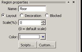
Now look at the section 2.
Again you see a Name where you can name the region for your convenience when you’ll be referencing the region from the script. Under you see three types of region:
Layout – means that it’s the main factor for deciding where in the z-position actor stands. Decoration – means that the region mixes its color with actors color (neon light example).
Blocked – is here for places where actor can’t enter.
You can also set a special scale for the actor (you can make him very small upon entering special region (some of you remember Sam and Max: Mystery Vortex location).
Let’s get back to our Node discovery and let’s try to add the last kind of Node. It’s the Region Entity.
In section 1 click on the yellow icon and select Add Region Entity. Immediately a red rectangle appears which acts as something in between Region and Sprite entity. You can manipulate it in the scene as you can the region by adding or removing vertexes and positioning it, but you can set the properties similarly to the Sprite entity. So what’s the purpose?
It’s one of the most useful nodes in WME. Imagine you have a door in this scene and you’ll never want to include them in the game design in other way then making actor say something like “This door is welded shut.” If you had to use Sprite entity for such interaction your game would gradually become very large. By using region entities you can exactly define what in the screen is interactive and what not. Also there are much more benefits coming from the fact that Region Entities are independent on the graphics which will become obvious when we’ll start doing a little game together. For now practice a bit and make this region entity you’ve just created cover the door and set its name to Door. Save your scene!
Before we get further on, I have a special task for you so listen closely. In your Project Manager navigate to scenes→warehouse→scr. This is the folder where all scripts are located. Double click the file scene_init.script and it opens.
You should immediately see the line which reads:
actor.SkipTo(400, 400);
change it so it will read:
actor.SkipTo(733, 562);
Now I know I am a bit ahead of you, but also I don’t like when you do something you don’t understand. scene_init.script is the file, which gets executed right when the scene is loading. So it’s the entry point of every scene. What we did was changing the actor position so it’ll be in the floor region which means that it will be able to walk. If your actor is positioned outside the region, it’s stuck in place and can’t move. You already played with actor positioning in the scene edit so you can easy see, that the provided values are reasonable for our floor region.
Ok, save the file and close it. Now in the Project Manager set the Startup Scene in Debugging settings Section to our warehouse.scene (browse for it). And let’s try our nice scene. Press f5 and walk around with molly. Of course ignore the bubbles, they’re here from the global demo setup, but focus on two things:
1. Door is interactive now. If you move over it with the mouse, the cursor change and the caption Door appears. Neat, isn’t it?
2. Ah-oh, you can walk directly through the boxes. That’s too bad. Gamers will throw rotten tomatoes at you, unless we fix it.
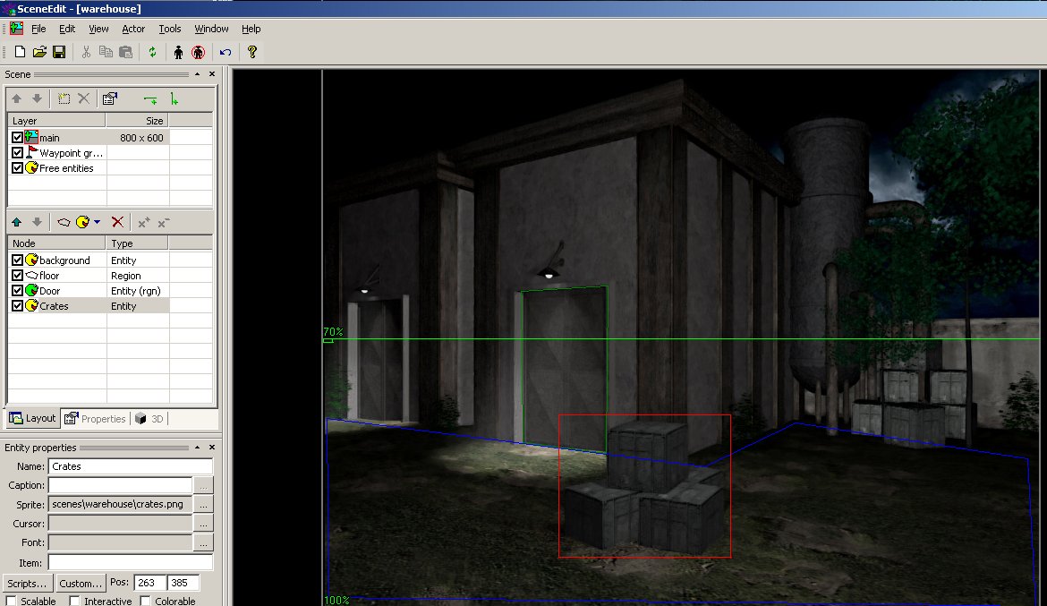
Before we can fix it, I have to tell you a secret about WME rendering. When WME draws a scene for you, it examines the layer, starts with the first node and draws it (in our case background), then it looks below and draws the next over it, then the next etc. So what do we have there? A way how to put objects in front of others! But how about our poor actor? How does she get sorted correctly? That’s where regions come in! You can see, that our actor must be positioned on some region otherwise she’ll refuse to walk. But this region is also positioned in the layer (see section 1). So let’s try a little experiment: add a sprite entity to our scene (yellow icon in section 1). Set the sprite to crates.jpg and position it exactly over the crates so it will replace them.
Trick: sometimes the positioning is a bit tricky. But you can use keyboard (arrow keys) to move entities around and also you can switch the reference background by pressing the space key. If you press space, your entity is invisible and this way you can very fast bring it to the correct position.
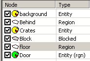
You should see the following order now:
Let’s save the scene (ctr+s) and test it. Hmm, Molly is walking all the time behind the crates. So it’s working somehow, but how to make her walking in front of them when she’s in front and behind when she’s behind? Let’s make our scene a bit more complicated.
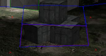
I’ll introduce you to two different methods how you can solve the crate problem. First will show the general way and the second will be a shortcut. Create two other regions. Name one “Behind” and the other “Block”. Position them that the behind is in the section 2 above the Sprite entity of crates and block is either directly above or directly below the sprite entity. Set the “Blocked” type to Block region. Positioning is done by two arrows in the section 1. It should look like this:
Now in the scene screen reshape the regions so they look like this:
And theoretically we’re set. So let’s save our scene and try it again!
Hmm, something is rotten. Molly doesn’t seem to find her way around the scene anymore. Why is that? We have to introduce a new concept – WME pathfinding.
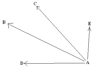
I’ll start to introduce this concept by two images:
This is the easy case. Actor standing in point A can directly “see” all points and she can walk whenever she wants as there is nothing blocking his way. By seeing I mean that she can connect the two points with a straight line.
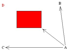
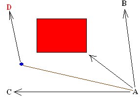
In this case, she can walk directly to point C and B, but D is blocked with an obstacle. To overcome this problem, WME introduces a system of waypoints. Waypoints are points in the scene which helps actor to finding his way around by creating temporary lines. Let’s look at our example again with a waypoint:
The blue circle is a waypoint and as you can see, actor finds her way to the point D easily because WME finds the shortest way how to guide actor with the help of waypoints.
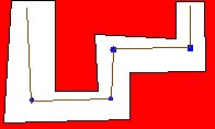
Last example is how to find a way through the little maze:
So enough theory and let’s see how it’s done in Scene Edit.
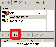
In section 4 select the layer Waypoint groups and then add a new waypoint group.
Select your newly created group, name it for example Crate and notice that two buttons x+ and x- got activated. You simply insert a waypoint by clicking on x+ and delete it by clicking on x- (also shortcuts are + and – on numeric keypad).
You can see 4 waypoints (red crosses) around the crates. It’s enough for actor to find her way around the whole scene. Just save and try it for yourself.
But there is still something rotten. It seems that the actor is sometimes not correctly covered with crates. Why’s that? Remember our hot spot discussion in the Sprite editor chapter? Well, that’s the cause! We're going to fix it right now.
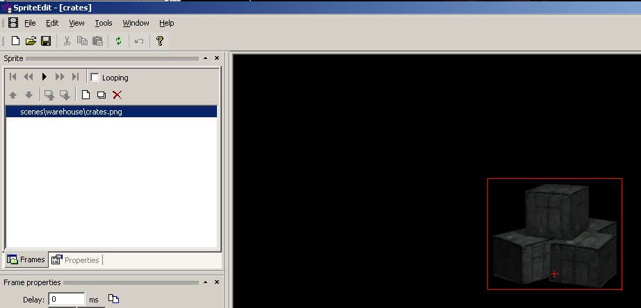
In the project manager add new sprite to the warehouse folder. Insert one frame (crates.png) and move the hotspot to the bottom of the crates. This hotspot falls in some region (our block region) and we can easily set the scene sorting order.
Save your sprite and then in Scene Edit change the sprite entity from png file to sprite file. Save and test the scene. Finally it works. That was quite some work, wasn’t it?
But I promised to show you a shortcut, didn’t I? The shortcut is called a free entity and it’s useful for smaller scene objects, so the crates are serious contenders for that.
But what are the free entities? They are entities which (in the similar way to your actor) are being drawn in respect to their position in the scene (in other words, in which region is positioned their hotspot).
Let’s try it. First select the “Behind” region and delete it (red X), then delete “Crates” sprite entity (red X). Resize the floor region so it covers the whole ground. Now switch to the layer called “Free entities” and create a sprite entity in the way you’re already used to. Name it crates and use the sprite file we’ve created earlier. Position it to the correct place, save your scene and test the game. See? It works in exactly the same way as before.
Last part of the Scene Editor discovery goes to section 4 which takes care of layers, scaling and rotation levels.
Let’s start with layers themselves. So far we used three layers: Main layer for the scene definition (regions, background), Waypoint layer for defining the path finding logic of our actor and Free entity layer we just recently discovered.
Now we can add more layers to our scene, but you’d be probably wondering why? There are two reasons one is visual and one is functional.
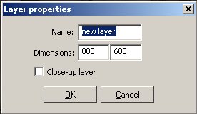
Click on the Add layer icon:
You’ll get the following screen:
Now you probably know that you can name your layer, but what are the other parameters? You can specify dimensions of your layer which are bigger or smaller than the main layer. But why to make the layer bigger if the game runs in the fixed resolution? WME supports scene scrolling and not only that, it supports parallax scrolling which means that you have a couple of additional layers of different size which when the game scrolls move in a different speeds which creates an illusion of a space. You can see this behavior in the demo street. The phone booth was placed on different layer. Go ahead – change in the project manager startup scene and look at the street scene so you’ll know what I mean. Similar to that is the room scene where there is a layer which contains the sky. Again you can see how the sky moves differently from the rest of the scene.
Second option is so called Close-up layer. This option means that if Close-up layer gets activated, it becomes the exclusive layer on the screen and all layers which are under this layer (the same order logic as in the layer itself applies) are not visible / active. You can use this option for example for a room with a table. If player clicks on table, actor goes there, close-up layer gets shown and player can see the table detail and interact with it.
On the layer bar you can also see two green lines. One is horizontal and one vertical. The horizontal green line is for defining scale. Your scene already contains two of those scale lines. In the real world you see something which is called perspective which is the reason why people far away appears to be smaller than they really are. In WME when using 2d actors we have to simulate how much gets the actor smaller when she walks to the camera or away from the camera. Setting scale lines is pretty simple. Either right click on existing scale line to adjust its properties or remove it altogether or simply drag is around to adjust y position. Let’s try some down-the-rabbit-hole effect. Select the scale line which reads 70%, set its properties and set the scale to 20. Then drag this scale line so it goes through the middle of the crates. Create a new scale line which goes through the light above the warehouse door. Set its value to 5. Now save your game and test it. Neat, eh?
The vertical green line is for defining rotation. This may be useful for someone as it can emulate the infamous fish eye camera effect but I don’t think I’d ever use it and it’s up to your experiments to play with it. Only note, that if you’re going to use this feature, you have to set the “Rotatable” attribute for your actor. We’ll get to it in the actor's chapter.
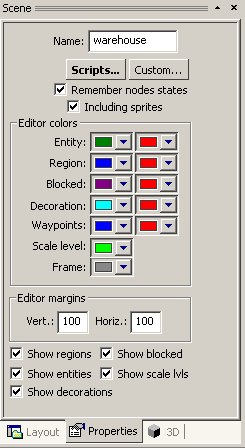
The last issue covered in this chapter is “Properties” tab located on the layer.
Here you can look at the scripts which are attached to the scene (by the default template you’ll find there always scene_init.script and scene.script). You can set some custom attributes for the scene, you can set if the Scene in the game remembers changes to the nodes (typically you want for example to hide some sprite entity and if you reenter the scene you want it still hidden). You can pick colors for depicting scene elements in the editor, set the margins and finally set up what elements should be visible in the editor.
On closing of the scene editor chapter I want to stress that I on purpose didn’t touch the 3D options. We’ll get to them much later when you’ll have the basics of the wme game covered. I know that some of you may be impatient to start your great 2 1/2 D games, but trust me, everything will be much faster if you went through the basics without skipping to much more complicated tasks.
So that’s it. You have mastered the core WME tools and it’s time to have a look on the way how the WME scripts work.

